Toolpath - User Guide
Toolpath converts G-code sliced by Cura (Marlin flavour, optionally with the ArcWelder plugin) into the
machine-readable .txt program format of the SEAM (High-Speed Extrusion) 3D printing test rig of the
Institute of Lightweight Structures, TU Chemnitz - an Omron NJ motion controller reading P001 XYZ,
G01, G02/G03 … R, G79 - and lets you check the result in 2-D per layer and in a
3-D simulation before the file goes onto the controller's SD card. It replaces the manually maintained Excel tables
that were used to produce these programs and handles the system-side limit of 2000 command lines per file
(the operators work with 1900 as a safe value) by automatic segmentation.
Developed as the Applied Engineering Project "Investigation into the software-based conversion of standard slicer programs to limited .txt G-code for a SEAM 3D printing test bench" (Advanced Manufacturing, TU Chemnitz, Professorship of Lightweight Structures and Polymer Technology; supervisors Prof. Dr.-Ing. habil. Daisy Nestler, Dipl.-Ing. (BA) Stefan Uhlmann, Gokul Varadharajan M.Sc.).
2. Toolbar & status chips
3. The three panes
4. What the converter does
5. Safe approach / exit
6. Splitting into several files
7. Export format check
8. 3-D simulator
9. Machine format reference
10. Cura profile & parameters
11. Remembered settings
12. Limits & tips
1. Workflow
- Slice in Cura (vase mode / spiralize works; the ArcWelder plugin may be on or off) and export the
.gcode. - Import or paste it into the Source pane and press Process & plot (Ctrl+Enter).
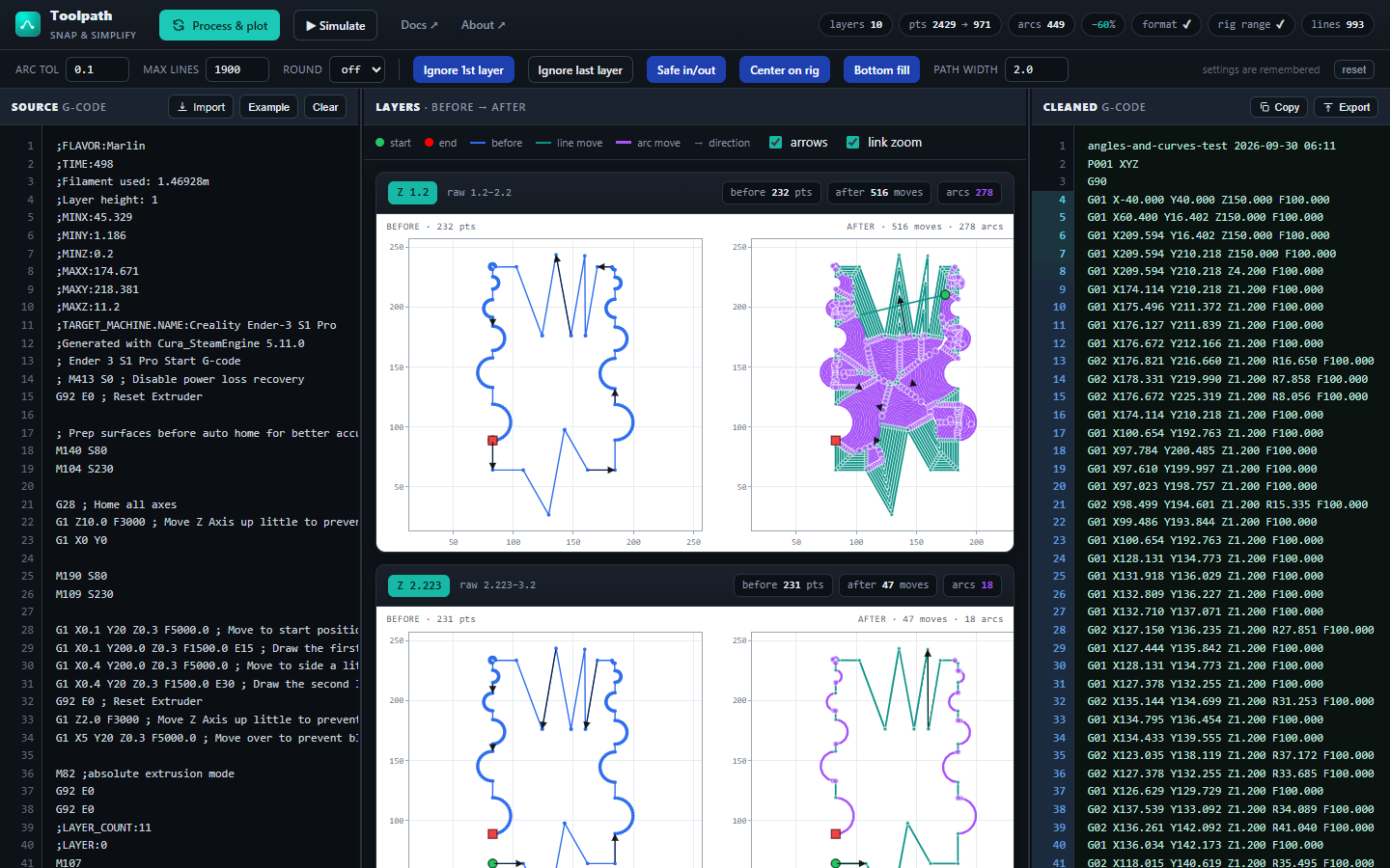
- Check the per-layer before → after plots and the format ✓, rig range ✓ and lines chips. If rig range is red, switch on Center on rig; for a solid bottom switch on Bottom fill. Press Process again after changing a setting.
- Press ▶ Simulate to watch the whole program in 3-D, from the park position to the end.
- Export - the file(s) are written exactly as the machine expects (CRLF, trailing spaces, 3 decimals).
2. Toolbar & status chips
The top bar holds the actions and the result chips; the second row holds the settings. Every setting is remembered in this browser (see §11).
| Top bar | Meaning |
|---|---|
| Process & plot | Run the converter on the current source text and redraw everything (Ctrl+Enter in the source pane does the same). |
| ▶ Simulate | Open the 3-D simulator with the processed program(s) in a new tab. |
| Docs / About | This guide and the project page. |
| Settings row | Meaning |
|---|---|
| arc tol | Resolution of the arc fitter in mm (default 0.1). Every original point and every segment midpoint must lie within this distance of the fitted circle. Smaller = more faithful, more lines; 0 disables arcs (pure G01). |
| max lines | Split the export into several files of at most this many lines (default 1900 - the rig's limit is 2000 command lines per file, 1900 leaves a margin; 0 = never split). See §6. |
| round | Optional rounding of X/Y/Z to n decimals before duplicate removal. off keeps Cura's values (the export always prints 3 decimals). |
| Ignore 1st layer | On by default. Drops Cura's first layer - with the profile below that is the thin 0.2 mm initial layer under 1 mm layers, which the paste extruder cannot print; the program then starts with layer 1 at Z = 1.2. |
| Ignore last layer | Off by default. Drops Cura's last layer (useful when Cura ends with a partial top layer). |
| Safe in/out | On by default. Approach the first point and leave the last one from beside the part, never across it. See §5. |
| Center on rig | Off by default. Shifts the printed part in X/Y so its footprint sits in the middle of the rig (X135 Y135); the toast shows the shift. Only the part moves: park, header and footer stay the same and the safe in/out is routed around the shifted part. Use it when the rig range chip is red - typically for a part placed near the edge of Cura's bed. |
| Bottom fill | Off by default. Gives the part a solid one-layer bottom: the first layer is filled with rings every path width mm (the field appears when the toggle is on; default 2.0 mm; the operators' plate programs use a line spacing of 1.4 to 3.3 mm). The rings are printed as one continuous path from the centre outwards and end one path width inside the wall start, so the wall and the spiral above follow without a stop. Concave outlines can split into islands; they are joined by straight hops across ground that is printed afterwards, and the toast says how many. Slits narrower than two path widths stay wall-only. The extra lines are handled by max lines (split into several files). |
| reset | Back to the defaults above. |

| Chip | Meaning |
|---|---|
| layers | Number of Cura layers found (;LAYER: blocks). |
| pts a → b | Points read from Cura → moves in the machine program (an arc counts as one move). |
| arcs | Number of G02/G03 moves emitted. |
| −x % | Reduction of moves. |
| format | ✓ when every export file passes the byte-level format check (§7); ✗ n otherwise - hover for the list of problems. |
| rig range | ✓ when every move (part, safe in/out, park) stays inside the rig's travel range; ✗ n otherwise, with a warning - past the range the POT/NOT end stops trip and the program aborts. Hover for the offending value and line. The range is provisional (X −50…340, Y 0…300, Z −2…150, the extremes of ~860 programs known to run, see §12). |
| lines | Lines of the program as the machine will read it (header + body + footer). With a split: n files · max m. Turns red above max lines. |
3. The three panes
Source (left)
Editable. Import a .gcode/.txt, paste, or load the built-in Example. The gutter shows
line numbers; for a Cura file the numbers are coloured per ;LAYER:. Edit any line and press Process again.
Layers (middle)
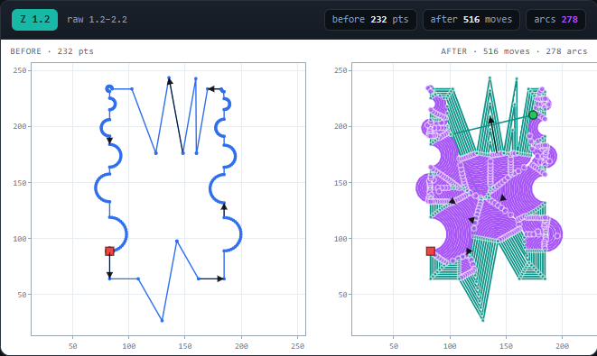
The badge shows the snapped Z and the raw Z range it came from. Green dot = start, red square = end, small
arrows = direction of travel; violet curves are G02/G03 arcs, teal segments are G01.
link zoom keeps BEFORE and AFTER on the same window while you pan/zoom; arrows can be switched off for dense layers.
Cards are drawn lazily while you scroll. The dividers between the panes are draggable.
Cleaned (right)
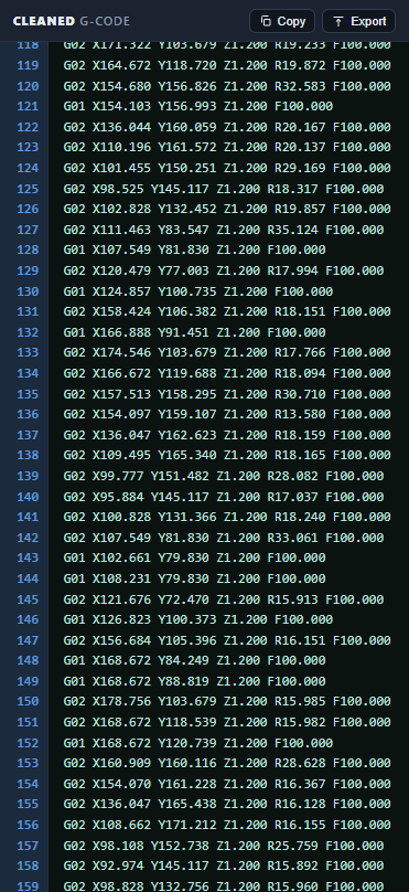
Copy copies the program(s); Export downloads p-MM-DD-xxx.txt with CRLF line endings;
xxx is the export serial 001 … 999 (kept by the server, back to 001 after 999). Line 1 of the exported
file (the program name on the HMI) is set to the same name. When the program is split, the pane shows a
----- file 2 / 3 ----- separator between files; it is never exported.
4. What the converter does
- Parse Cura moves.
G0/G1are points.G2/G3 … I J(Cura's ArcWelder plugin) are expanded into points, so a welded file and the plain file give the same result. Cura's start-gcode (before the first;LAYER:) and end-gcode (after the last;TIME_ELAPSED:, and anything underG91) are never printed. - One Z per layer. Cura's spiralize starts layer n at its nominal height and ramps up by one layer thickness (0.2→0.4, 1.2→2.2, 2.2→3.2 …). The planar equivalent is therefore the layer's start height: layers become 0.2, 1.2, 2.2 … exactly. (Snapping to the top of the ramp put every layer one layer too high and left a ~2 mm air gap under layer 1 - that was the cause of the missing beads in the first two layers.)
- Remove duplicates and, optionally, round. With Center on rig the whole part is shifted in X/Y first (before any plot is drawn, so BEFORE and AFTER show the shifted part).
- Bottom fill (optional). The first layer's outline is offset inwards every path width, the rings are chained into one path from the centre outwards and put in front of the first layer at the same Z. The fill appears only in the AFTER plot.
- Fit arcs - ArcWelder's rules: a circle through the first / middle / last point of a run of ≥ 4 points; every
point and every segment midpoint within arc tol; monotone sweep; arc length within 5 % of the polyline; radius
between 1 mm and 10 m. Arcs are cut into ≤ 180° pieces because the machine takes
R, notI J. - Guarantee valid arcs. Every emitted arc satisfies
R ≥ chord/2(R rounded up to 3 decimals) and has a non-zero chord. The Omron radius-mode circular interpolation faults on anything else and the program stops on that line - this was the cause of the "stops at the same line every time". - Wrap with the machine header (title,
P001 XYZ,G90, park position), the safe approach, the safe exit, the M-code footer andG79.
5. Safe approach / exit
The paste extruder cannot stop the flow, so the head must never travel across the part - otherwise material lands on the first layer before it is printed, or on the top layer after it. With Safe in/out the program does what the hand-written reference programs do:
- A box is put around the part's footprint (all points incl. arc bulges, + 10 mm).
- Approach: park
X-40 Y40 Z150→ along the box corners at Z150 → to the box side nearest the first point → straight down beside the part to first-layer Z + 3 mm → into the start point from the side. - Exit: from the last point sideways out to the nearest box side while rising 3 mm (a wipe) → straight up beside the part (to Z150, or higher if the part is taller) → around the box → park.
The corner route is always the shorter way round. With Safe in/out off you get the old direct diagonal.
6. Splitting into several files
The SEAM controller accepts at most 2000 command lines per file, which made complex geometries impossible without
manual segmentation. Set max lines (default 1900). The body is cut between layers so that every file, including its own header, footer and
in/out moves, stays under the limit. Each file is a complete program; the exit of file n and the approach of file
n+1 are routed around the whole part's box, so re-entering at layer 40 never crosses the lower 39 layers.
Export downloads p-MM-DD-xxx-01.txt, -02.txt, … (one serial for all parts; the browser may ask once to allow several downloads) -
run them on the machine in that order. The simulator plays them as one continuous process.
7. Export format check
After every Process the exact bytes the browser will export are checked against the convention of the programs that are
known to run on the machine (e.g. kleeblatt-01.gcode). The format chip turns red and lists the problems
if anything deviates; Export still works but warns. Rules:
| Encoding | UTF-8 without BOM, no TAB characters, no ; comments. |
| Line endings | CRLF on every line including the last. |
| Line ends | Every line ends with exactly one space before CRLF (required by the FB manual). |
| Numbers | X, Y, Z, R and F with exactly 3 decimals; F on every move. |
| Structure | Line 1 title, line 2 P001 XYZ, line 3 G90, line 4 a full G01 X Y Z F start position, last line G79. |
| Grammar | G01 X Y Z F · G02/G03 X Y Z R F · Mnnn [value] · G04 t · G90/G91. |
8. 3-D simulator
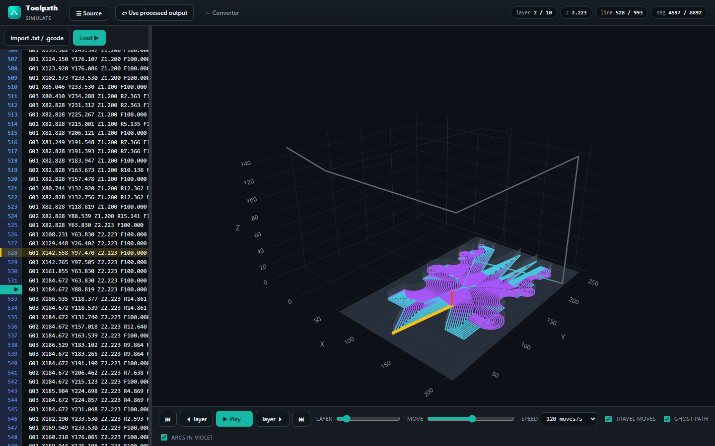
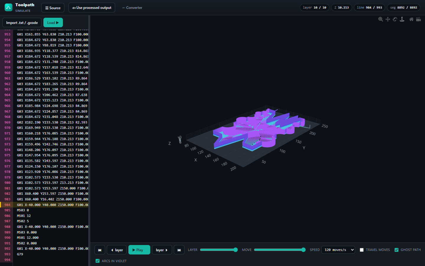
Open it with ▶ Simulate (loads the processed program) or go to /simulate and Import any
machine .txt/.gcode - the reference programs load as they are; a Cura file is converted first.
| Control | Meaning |
|---|---|
| Mouse / touch | Drag to orbit, wheel or pinch to zoom, right-drag to pan. Hover a path for layer / Z / X / Y. |
| layer slider, ⏴ layer / layer ⏵ | Show the part up to the end of a layer. |
| move slider | Scrub through every single move, incl. travel. |
| Play / speed | 1, 5, 30, 120, 500, 2000 moves per second, or one layer per second. ⏮ resets, ⏭ shows the whole part. |
| travel moves | Draw park / approach / exit legs (grey). Untick to frame the part only. |
| ghost path | Faint outline of the whole part behind the progress. |
| arcs in violet | Colour G02/G03 segments differently from G01. |
| ☰ Source / divider | Hide the source pane, or drag the divider to resize it. The source shows the program with coloured line numbers per layer. |
| Line cursor / ▶ on a line number | While the program plays (or when you scrub), a yellow bar marks the line of the current move and the source scrolls with it. When stopped, hover a line number and click its ▶: the head jumps to the end of that line's move and the move is drawn thick yellow in 3-D. A line without a move (header, M-code) shows the move before it. Play clears the highlight. Only for machine programs; a Cura file is converted first, so its lines don't match. |
| Chips | layer k / n · Z · line = program line of the current move / total lines · seg = drawn segments (arcs are expanded into ~5° pieces for display, so seg > lines). |
| Keyboard | Space play/pause · ←/→ previous/next layer. |
9. Machine format reference
jetcone 2026-09-17 10:42 2/3                        ← title (line 1)
P001 XYZ                                    ← axes
G90                                         ← absolute
G01 X-40.000 Y40.000 Z150.000 F100.000      ← park / start position (must have X Y Z F)
G01 X15.319 Y86.399 Z150.000 F100.000       ← safe approach …
G01 X30.418 Y86.399 Z3.200 F100.000
G01 X30.418 Y100.338 Z0.200 F100.000        ← first print move
G03 X37.536 Y99.648 Z0.200 R10.724 F100.000 ← arc: end point, radius, ≤ 180°
…
G01 X86.007 Y133.599 Z11.200 F100.000       ← safe exit …
M503 0                                      ← footer M-codes (extruder / press)
M501 12
M502 5
G01 X-40.000 Y40.000 Z150.000 F100.000
M503 0.000
M501 12.000
M502 0.000
G01 X-40.000 Y40.000 Z150.000 F100.000
G79                                         ← end
In the output pane the title (line 1) shows the imported file name, the conversion date/time and, when split, the
part number n/N. On Export it is replaced by the file name (p-09-17-012, split
p-09-17-012-03), which appears as PRG-Name on the HMI. That name stays within the HMI's
16 characters + .txt.
Every line above ends with a space and CRLF. G02 = clockwise, G03 = counter-clockwise, seen from above.
M001–M499 wait for acknowledgement, M501–M999 do not. The title, park position and footer M-codes
live in wrap_program() in app.py.
10. Cura profile & parameters
Download the profile used for this machine and import it in Cura via Preferences → Profiles → Import: tu-chemnitz-toolpath.curaprofile (made for the Ender-3 S1 Pro definition - the printer definition only sets the build volume; the converter ignores everything machine specific).
| Cura setting | Value | Why |
|---|---|---|
layer_height | 1 | Bead height of the paste extruder. The converter puts every layer at its Cura start height, so this is the Z step of the machine program. |
line_width | 1 | Bead width - determines the perimeter offset Cura applies. Match it to the nozzle. |
magic_spiralize (vase mode) | True | One continuous outer wall per layer, no travel moves, no seam. Cura's continuous Z ramp is flattened by the converter. |
smooth_spiralized_contours | False | Keeps the wall on the model contour; smoothing would move points off the true shape before arc fitting. |
wall_line_count | 1 | Single wall - the machine prints one bead. |
top_layers / bottom_layers | 0 / 0 | No solid top/bottom skins (spiralize requires this). If you need a bottom, print it as a separate program. |
infill_sparse_density | 100 (unused) | Irrelevant in vase mode; kept at 100 % so a non-spiralized test slice gives a solid grid. |
inset_direction | outside_in | Outer wall first, if more than one wall is ever used. |
z_seam_type | sharpest_corner | Puts the layer start on a corner, where the approach/exit and the layer change are least visible. |
retraction_enable | False | The paste extruder has no retraction; leaving it on only produces E moves that are trimmed anyway. |
adhesion_type | none | No skirt/brim/raft - those would be printed as part of layer 0. |
bridge_settings_enabled | True | Harmless; only changes speeds, which the converter drops. |
arcwelder_enable | False | Optional. The converter fits arcs itself with the same rules. If you turn the plugin on, its G2/G3 I J output (also 3-D arcs) is accepted and re-fitted planar. |
arcwelder_resolution | 0.1 | Only used if the plugin is on; same meaning as arc tol. |
| Initial layer height | = layer height | Recommended. The default 0.2 mm first layer cannot be printed with a 1 mm bead - that is why Ignore 1st layer is on by default. With initial layer height = 1 mm you can switch it off. |
What is ignored from the Cura file: all extrusion data (E values, M82/M83, G92 E0), feed rates
(F - the machine program uses its own), temperatures and fan (M104/M109/M140/M190/M106/M107), acceleration
(M204), comments and ;TYPE:/;MESH: markers, the start-gcode before the first ;LAYER:
and the end-gcode after the last ;TIME_ELAPSED: (homing, wipes, "present print"). Only the XY(Z) geometry of the
G0/G1/G2/G3 moves inside the layers is used, so extrusion, speed or temperature settings in Cura never influence the
result - you do not need to tune them.
11. Remembered settings
Every setting you change is stored in the browser's localStorage under the keys toolpath.settings.v1
(converter: arc tol, max lines, round, Ignore 1st/last layer, Safe in/out, Center on rig, Bottom fill + path width) and toolpath.sim.v1 (simulator: speed,
travel / ghost / arcs toggles, source-pane width). localStorage has no expiry - the values survive browser restarts,
updates of Toolpath and years of not using it; they are only lost if you clear the site data for this address or use another
browser / private window. reset in the settings row restores the defaults. The processed program handed to the simulator
(sim_gcode) is stored the same way.
12. Limits & tips
- Line limit. The controller accepts 2000 command lines per file (the FB manual still says 1000); the operators use 1900. The header, footer and safe in/out moves cost about 25 lines per file, the rest is geometry. max lines splits automatically - a split costs nothing but a short exit / re-entry.
- Reducing the line count. Every corner of the STL needs at least one line; only smooth curves collapse into arcs. A larger arc tol (e.g. 0.2 mm) merges more of a curve into one
G02/G03but starts to erase small features; a coarserlayer_heightreduces the number of layers linearly. A faceted STL (coarse mesh export from CAD) produces a corner at every facet - export STLs with a fine angular tolerance so curves are curves, and design parts with smooth contours where possible. - Titles longer than 20 characters and programs without the trailing space have run too, but the export sticks to the strict form because it is what the manual and the best reference programs use.
- Rig travel range. The rig's limits are not documented; the values in
RIG_LIMITS/RIG_CENTER(top ofpipeline.py) come from the programs known to run. Measure them once: in Service → Achse X/Y/Z jog slowly towards each end stop and read Istposition just before POT/NOT, then enter the values there. - Bottom fill. The fill is one continuous path, so a concave outline that splits into islands needs straight hops between them (counted in the toast); they cross ground that is filled afterwards. Slits narrower than two path widths get no rings. A path width larger than the part, or an empty field, adds nothing - the toast then warns.
- Safe in/out uses a rectangular box around the part. For strongly concave parts (e.g. a three-lobed rotor) the hand-written programs thread between the lobes; the box route is longer but always safe.
- Reference programs and the FB manual are in the project's documentation folder;
python test_pipeline.pyruns the built-in checks (arc validity, Z snap, safe paths, split, format, rig range / centring, bottom fill) andpython check_export.pyexports through a real browser and re-validates the files.